A guide for Connecting LED Strips to the controller.
Power Distribution
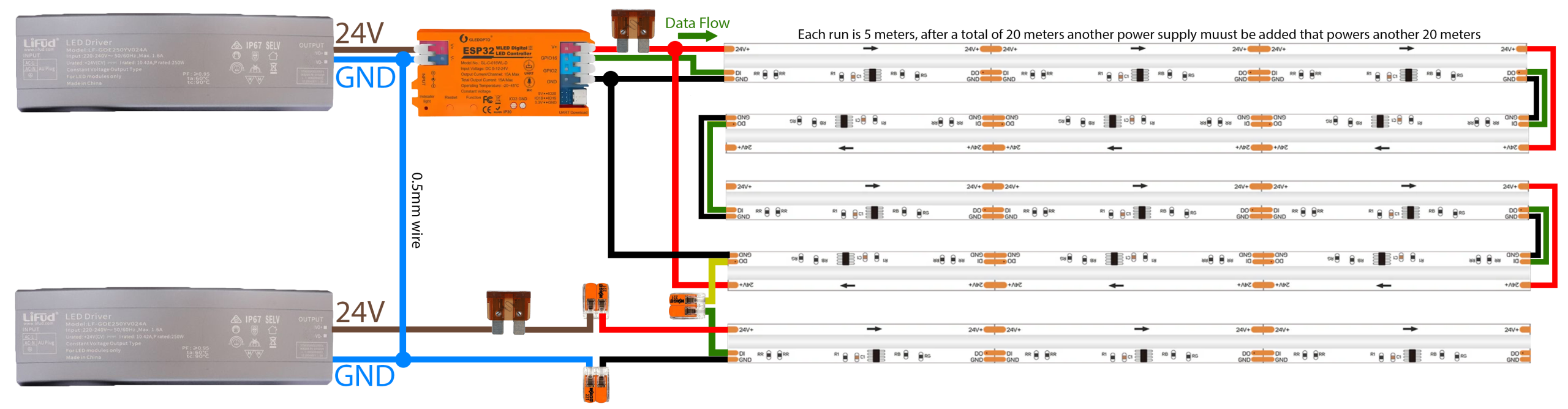
Each LED strip run is 5 metres. PSU 1 powers the first 20m (4 strips) and if you need to extend beyond 20m, a second PSU is added to power the next 20m (another 4 strips).
Before anything else, connect a 0.5mm² wire from the GND on PSU 1 to the GND on PSU 2 — this links the two power supplies together. Also run a ground wire from PSU 2 back to the GND on the controller. If you skip these ground connections your lights will flicker or not work.
First 20m (Strips 1–4)
Connect power and ground from PSU 1 to the ESP32 controller. Run a power and ground wire from the fuse to the start of strip 1. At the 10m mark (between strip 2 and 3), cut the red (+) wire. Run a second power and ground wire from the fuse all the way to the end of strip 4 — this powers strips 3 and 4 from the back end.
Result: PSU 1 powers the first 10m from the front and the second 10m from the back.
Extending Beyond 20m (Strips 5–8)
Repeat the same process with PSU 2 starting from strip 5. At the 30m mark (between strip 6 and 7), cut the red (+) wire. Run a second power and ground wire to the end of strip 8.
Result: PSU 2 powers strips 5–8 the same way.
Data Wire
Run the green data wire from the controller to the start of strip 1, then continue it through each strip. At the join between strip 4 and 5, strip the wire sleeves and connect them using a Wago clip.
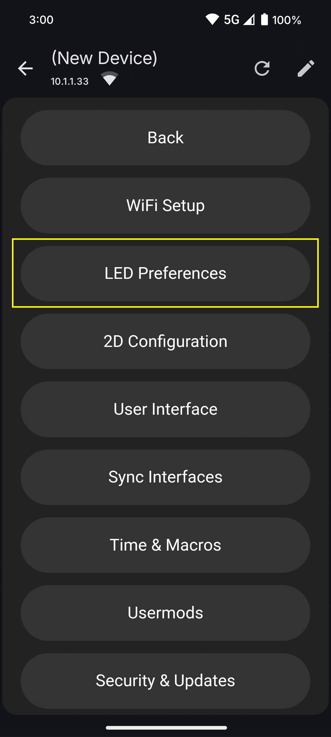
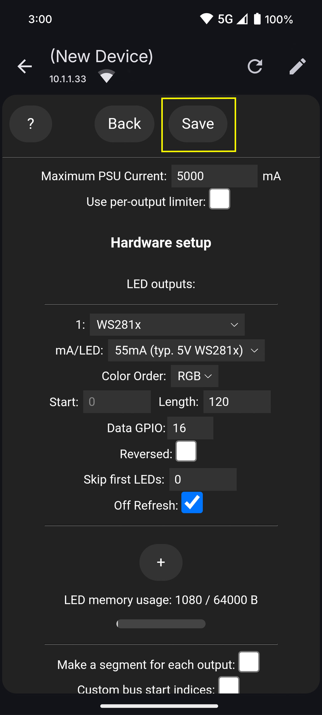
In the app or web UI, go to Config (gear icon) → LED Preferences. Under the Hardware Setup section find LED Outputs and configure the following:
Output #1 → LED strip
Chipset = WS281x (StarEFX LED Strip)
Data GPIO = 16
To find your LED length, divide the total strip length in mm by 41.666 (the length of each pixel). For example, a 20m strip = 20,000mm ÷ 41.666 = 480 pixels. Enter this value under Output #1 → Length.
Note: every 5m strip has 120 pixels.
Once done, click Save at the top of the page.
If only part of the strip lights up, the length value is too short — increase it until the full strip is covered.
Images
Segments Check
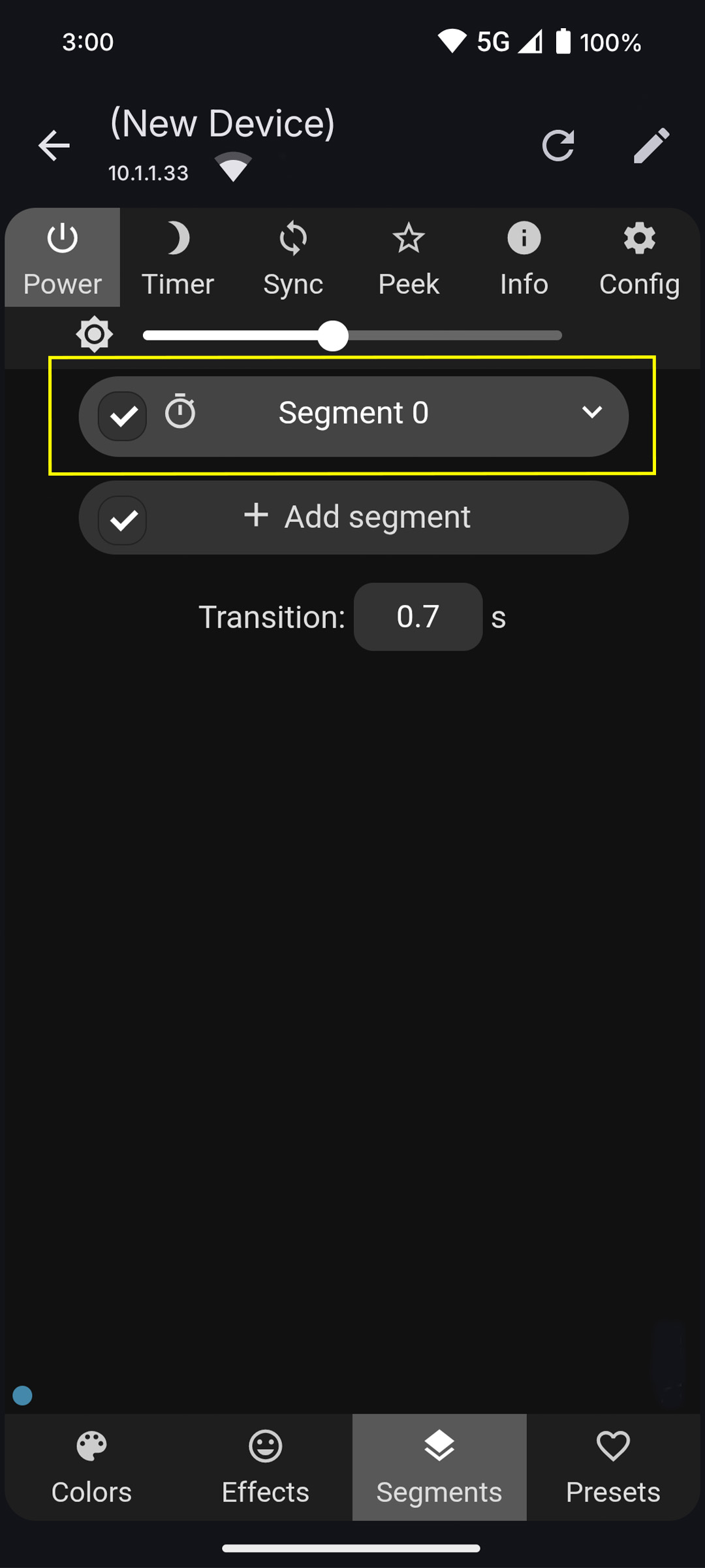
Go to the Segments tab and click the dropdown on Segment 0 to expand it. Set the following:
Start LED = 0
Stop LED = the LED length you entered in LED Preferences (e.g. 480 for a 20m strip)
Click the tick to save. If the LEDs don’t cover the full strip, the Stop value is too low — increase it to match your LED length.
If the LEDs don’t cover the full strip → the Stop value doesn’t match your LED length.