A guide for Connecting LED Strips to the controller.
Power Distribution
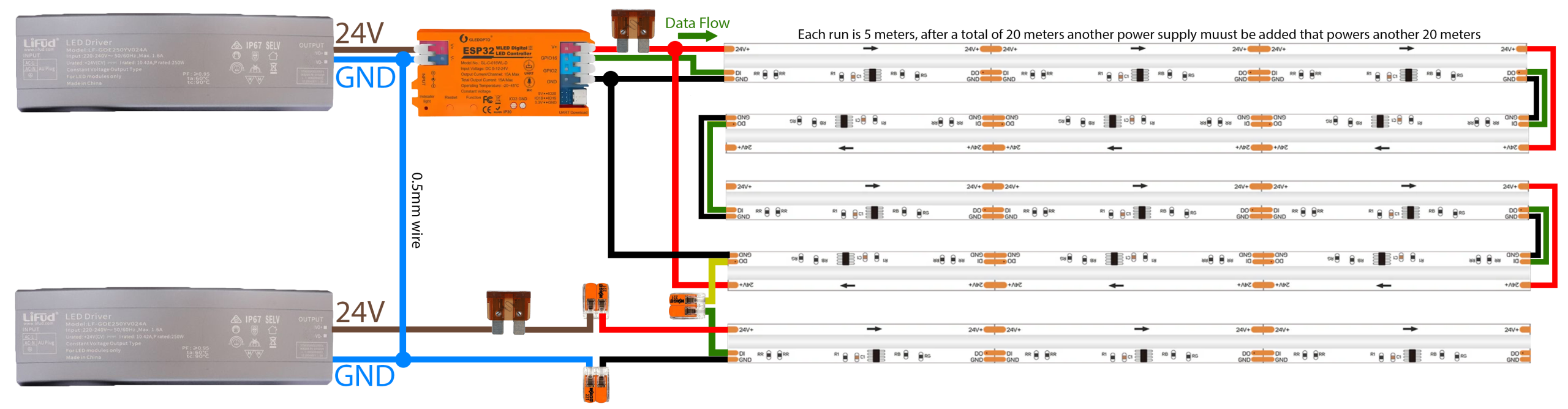
Connecting the Power Supply Grounds
Before doing anything else, take a piece of 0.5mm² wire and connect the GND (Negative) screw on the top power supply directly to the GND (Negative) screw on the bottom power supply.
If you forget this, your lights will flicker rainbow or not work.
Wire the Top Half (First 4 Strips | 0m – 20m)
Connect power and ground from PSU 1 to your ESP32 Controller.
Run a power and ground wire from the fuse to the start of the 1st LED strip.
Go to the point where the 2nd strip ends and the 3rd Strip begins (the 10m mark). CUT the RED (+) wire between these two strips.
Run a long Power (Red) and Ground wire from the fuse to the very end of the 4th Strip (the 20m mark). This powers strips 3 & 4 backwards.
Result: PSU 1 powers the first 10m from the front, and the next 10m from the back.
Wire the Bottom Half (Next 4 Strips | 20m – 40m)
Run Power and Ground from the Bottom PSU (via fuse) to the start of the 5th Strip (the 25m mark).
Go to the point where the 6th strip ends and the 7th Strip begins (the 30m mark). CUT the RED (+) wire between these two strips.
Run a second set of power and ground wires from the fuse all the way to the very end of the 8th/Last strip (the 40m mark).
Result: PSU 2 powers the first 10m from the front, and the next 10m from the back.
Connect the Data (The Green Wire)
Run the Green wire from the Controller to the start of the 1st Strip.
Connect the Data wire from the end of the 4th Strip (20m mark) to the start of the 5th Strip.
Tip: Because the connectors are cut off, strip the Green data wire sleeves and wire them together using a Wago clip.