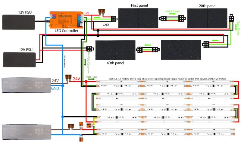
This guide covers wiring and configuring both StarEFX Pulse panels and an LED strip running from the same controller. The panels connect to Output #1 and the LED strip connects to Output #2, allowing you to control them together or independently.
Power Distribution (StarEFX panels)
Up to 20 panels — single PSU
Connect PSU 1 to the LED controller and run a second power wire to the last panel. This feeds power into both ends of the chain, ensuring consistent voltage across the full run.
More than 20 panels — add a second PSU
With a single PSU the voltage will drop over a long run, so a second PSU is needed from panel 21 onwards.
The first PSU continues to power the first half of the run, and the second PSU takes over from panel 21 to the last panel.
The grounds from both PSUs must be joined together at one point — at the controller or anywhere convenient on the installation.
Data Connection
Controller → Panel 0
Panel 0 is the start of the chain. Its input connector plugs into the output of the LED controller. The data signal, positive voltage, and ground all leave the controller together and enter panel 0 first.
Panel → Panel
As each panel is mounted, plug the output link cable from the previous panel into the input connector of the new panel. Follow the numbered installation order — panel 0 to panel 1, panel 1 to panel 2, and so on. Do not skip panels or connect them out of order.
Power Distribution (LED strip)
Each LED strip run is 5 metres. PSU 1 powers the first 20m (4 strips) and if you need to extend beyond 20m, a second PSU is added to power the next 20m (another 4 strips).
Before anything else, connect a 0.5mm² wire from the GND on PSU 1 to the GND on PSU 2 — this links the two power supplies together. Also run a ground wire from PSU 2 back to the GND on the controller. If you skip these ground connections your lights will flicker or not work.
First 20m (Strips 1–4)
Connect power and ground from PSU 1 to the ESP32 controller. Run a power and ground wire from the fuse to the start of strip 1. At the 10m mark (between strip 2 and 3), cut the red (+) wire. Run a second power and ground wire from the fuse all the way to the end of strip 4 — this powers strips 3 and 4 from the back end.
Result: PSU 1 powers the first 10m from the front and the second 10m from the back.
Extending Beyond 20m (Strips 5–8)
Repeat the same process with PSU 2 starting from strip 5. At the 30m mark (between strip 6 and 7), cut the red (+) wire. Run a second power and ground wire to the end of strip 8.
Result: PSU 2 powers strips 5–8 the same way.
Data Wire
Run the green data wire from the controller to the start of strip 1, then continue it through each strip. At the join between strip 4 and 5, strip the wire sleeves and connect them using a Wago clip.